Diagrams Power Steering Hoses 1998 Gmc C3500 With Hydro Boost
Hydro-boost power assist was introduced in 1973 by Bendix as an alternative to the vacuum booster. The hydro-boost uses the hydraulic pressure from the power steering system to provide the driver assist in applying the brakes. There are three reasons why a vehicle may be equipped with hydro-boost instead of a vacuum booster:
Click Here to Read More
- There is no vacuum source available, as in diesel engines, or the vacuum source available is too weak to adequately supply a vacuum booster.
- There is limited space available for the power assist device.
- The vehicle requires more assist than is available from a vacuum booster.
Hydro-boost has been used on a variety of vehicles since its introduction and OEM applications presently include:
* 1996 and newer Cobras and all V8 Mustang;
* Most 2500 and 3500 series GMC/Chevy trucks;
* Dodge Ram equipped with Cummins turbo diesel;
* Ford Super Duty series trucks equipped with Diesel; and
* All Hummers – including the H2.
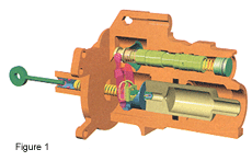
Proper diagnosis of hydro-boost related problems requires an understanding of how the system works. A typical hydro-boost is shown in Figure 1. The hydro-boost is plumbed in line with the steering gear. The power steering pump supplies pressurized fluid for both the power steering gear and hydro-boost.
 Spool Valve
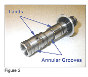
Fluid flow in and out of the hydro-boost is controlled by what is known as a spool valve. Spool valves are used in a variety of hydraulic components, such as the valve body of an automatic transmission. A spool valve is basically a hollow cylinder with a number of rings machined into it (see Figure 2). The surface of the spool valve is highly polished to form a sealing surface. The raised portions of the cylinder are called lands while the indentations are called annular grooves.
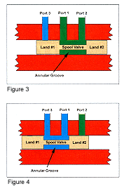
Figure 3 shows a simplified spool valve positioned in a bore with three ports. The path of the pressurized fluid from port 1 is determined by the position of the spool valve. The spool valve is positioned in figure 4 to allow fluid flow from port 1 to port 2 while port 3 is blocked by land #1. Figure 4 shows the spool valve moved to the left which changes the fluid flow. The fluid flow is now from port 1 to port 3 with port 2 being blocked by land #2. The spool valve in a hydro-boost works in a similar fashion.
 Hydro-boost Construction
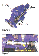
Figure 5 shows a cutaway of a hydro-boost with all the major components labeled. These include the housing, power chamber, input rod assembly, a lever assembly, a power piston, spool valve assembly and an output rod. The housing is fitted with three ports as identified in Figure 6. The spool valve fits into a precisely machined bore that is part of the hydro-boost housing as shown in Figure 7. The fit between the spool valve and the bore is such that it creates a seal while at the same time allowing enough fluid between the lands and bore to provide lubrication. The spool valve's position is determined by the lever assembly which is connected to the input rod.
Pedal Unapplied
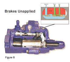
When the brakes are unapplied the spool valve is positioned as shown in Figure 8. In this position the pressurized fluid from the power steering pump is allowed to flow to the steering gear, but not into the power chamber. The spool valve vents the power chamber to the return line of the power steering pump reservoir. 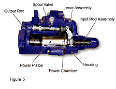
Pedal Applied
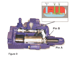
Once the brake is applied, the input rod moves forward (left) to the power piston assembly. The piston return spring is preventing the power piston and pin "A" from moving forward. This lack of movement causes the input rod to force the travel limiter valve assembly into the power piston which results in pin "B" moving forward. The lack of movement at pin "A" and forward movement of pin "B" causes the lever to pivot at pin "A". The top of the lever moves forward (left) which results in moving the spool valve (See Figure 9).
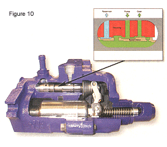
 The forward movement of the spool valve closes the reservoir port which seals off the power chamber. Continued movement of the spool valve opens the pressure port from the power steering pump allowing pressurized fluid into the power chamber while at the same time maintaining the fluid flow to the steering gear. The pressure in the power chamber causes the power piston to move forward (left) which applies the brakes through the output rod (See Figure 10).
Pedal Released
Once the brakes are released, the spool valve return spring pushes the spool valve back to its rest position. This vents the pressure in the power chamber to the power steering pump reservoir through the return line. The power piston and lever assembly are returned to their rest position by return springs which in turn brings the brake pedal back to an unapplied position.
 Back-Up
Similar to the vacuum booster, the hydro-boost is equipped with a backup or reserve in case the source of pressurized fluid is lost. A failure in the power steering system, such as a broken hose, broken power steering pump drive belt, or failed pump, would result in a loss of pressure to both the hydro-boost and steering gear. The hydro-boost uses a high-pressure accumulator to store power steering fluid under pressure in the event of a failure. There are two types of accumulators used, some hydro-boost units use an external accumulator, while others incorporate the accumulator in the power piston. The accumulator could be either of the spring-loaded variety or nitrogen-gas type.
In the event of a loss of pressurized fluid, the accumulator will provide two to three power assisted stops. Upon the first application of the brakes after an engine stall or loss of power steering, you would find approximately 60 to 75% of the normal assist available. If you were to release and apply the brakes again, you would find approximately 30% to 40% assist, then again approximately 10% to 20%, until you have depleted all stored reserve assist. Once you have depleted all of the stored pressure, the brakes will no longer have power assist and will be manual in their operations.
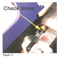
 During normal operation, the accumulator is charged by pump pressure though a check valve assembly (See Figure 11). The check valve allows fluid into the accumulator, but prevents it from escaping. When the pressure in the power chamber is lost due to a failure, the input rod linkage will override the power piston linkage and cause the check valve to be opened. The open check valve will release the stored fluid in the accumulator into the power chamber which will provide the power assist.
Pedal Feel
The hydro-boost generates a different pedal feel than a vacuum booster. Basic function can be checked by pumping the brake pedal until hard with the engine off and then starting the engine while maintaining slight pedal pressure. Proper operation should result in the brake pedal sinking down and then pushing back up against your foot. The sinking of the pedal when the engine was started is a result of the power chamber being pressurized. Once the power steering system is at full pressure, it results in the pedal pushing back against your foot pressure.
 Diagnosis
The hydro-boost requires a constant source of pressurized power steering fluid for proper operation. Problems in the power steering system will be reflected in the operation of the hydro-boost.
Accurate diagnosis of a hydro-boost power assist device depends on combining an understanding of their function with a logical diagnostic approach. Hydro-boost problems usually break down into the following categories:
 * Noise problems;
* Slow or incomplete pedal return;
* Over sensitive braking; and
* Self applying brakes Note: Each of these is covered in the following sections.
Noisy Booster
1. Confirm complaint making sure to note type of noise and when it occurs. If the noise occurs during high brake pedal efforts or quick pedal release, go to step 2. If the noise occurs during low brake pedal effort, engine idle – no pedal effort, or normal driving conditions, go to step 3.
2. Noise occurs during high brake pedal efforts or quick pedal release: See normal operation noises listed below. Most likely the noises being heard are normal based on the type of conditions.
3. Operate the vehicle until the engine is at normal operating temperature. Duplicate the operating conditions above and listen for the noise.
4. Compare results with the normal noises listed under the more info section and with a known acceptable system.
Normal Operation Noises
Properly operating hydro-boost units will produce certain noises. These noises occur, for the most part when the brake pedal is manipulated in a manner not associated with everyday driving habits. The general categories of normal operating noises are (1) hissing noises and (2) clunk/clatter noises.
The hydro-boost will emit normal hissing noises when above-normal brake pedal efforts are applied (40 lbs. and up). The hiss sounds particularly noticeable with the vehicle motionless and will increase in intensity as pedal pressure increases above 40 lbs. and system operating temperature increases. Loud hissing sounds at or below normal (20 to 25 lbs.) pedal effort warrants investigation.
Clunk, clatter or clicking noises will be heard when the brake pedal is quickly released from hard (50 to 100 lbs.) pedal efforts.
Slow or incomplete pedal return:
1. Run pump at fast idle.
2. Pull the brake pedal rearward with approximately 10 lbs. force and release. Measure the distance to the floorboard.
3. Make 100-lb. brake application. Release brake pedal and measure distance to floorboard. The brake pedal should return to its normal position (step 2). If measurements are the same, go to step 5.
4. If the brake pedal does not return properly, check the pedal to be sure it is operating freely. Correct any sticking or binding as necessary.
5. If brakes are self applying and pedal is free, check for obstruction in the return line or a kinked connection between hydo-boost and pump reservoir. If obstruction or kink is found, go to step 6, otherwise go to step 7.
6. Remove obstruction or replace line as required. If condition remains, check for a damaged reaction end. If damaged the hydo-boost should be replaced or repaired.
7. If brake pedal is free of any binding conditions and return line is free of obstructions, remove the master cylinder cover.
8. Observe the brake fluid in the reservoir while rapidly depressing the brake pedal one inch.
9. Fluid surface should have some movement or spout in the forward reservoir section. Minor spouting may occur in the rearward reservoir. If no movement or spouting of fluid occurs in forward reservoir, the hydro-boost unit is defective and must be replaced or repaired.
Excessive pedal effort – brake pedal chatter – pulsation and/or leaks:
Perform Basic Test:
1. Engine (pump) off, depress and release the brake pedal four times to deplete all hydraulic pressure from hydo-boost.
2. Depress brake pedal and hold with light pressure then start the engine. If the power section is operating properly the pedal will fall slightly and then hold. Less pressure will be needed to hold the pedal in this position. If the power section is NOT operating, go to step 3, otherwise go to step 4.
3. If power section is not operating properly, check pump reservoir level. If level is low, add fluid and repeat basic test plus Hydraulic Leak Test (Steps 4 to 5). If fluid level is good, go to step 6.
4. Steering Hydraulic Leak Test: Thoroughly clean the hydo-boost unit and all hose connections. Start the engine and run at idle speed. If the hose fittings do not leak go to step 5.
5. Check the hydro-boost for leaks. Apply the brake pedal with approximately 100 lbs. force and hold while checking hydro-boost hose fittings for leaks. Do not hold brake pedal at 100 lbs. effort for more than five seconds at a time. If the hydo-boost leaks, it is defective and should be replaced or repaired. If no leaks are found in the hydro-boost or hoses, do not repair or replace them.
6. Fluid level good: Check tension and condition of drive belt. If the drive belt is loose or damaged, tighten or replace as required and repeat the basic test (Steps 1-2). If pump speed is slow, adjust and repeat basic test. If pump speed is OK, perform pump flow and relief pressure test.
7. If pump output is below minimum specification, replace and repeat basic test. If all test and checks are OK, the booster is defective and should be replaced or repaired.
8. If power section is operating, perform the following steps in order.
9. Hydro-boost accumulator pressure retention test: Run pump to medium speed, apply brake pedal force to 100 lbs. for not more than five seconds and then stop engine.
10. Wait 90 seconds and apply the brakes. Two or more applications should be power assisted. If applications are not power assisted the hydro-boost is defective and should be replaced or repaired. If applications are power assisted, go to next step.
11. Thoroughly clean the hydo-boost unit and all hose connections. Start the engine and run at idle speed. If the hose fittings do not leak, go to step 5.
12. Check the hydro-boost for leaks. Apply the brake pedal with approximately 100lbs force and hold while checking hydro-boost hose fittings for leaks. Do not hold brake pedal at 100 lbs. effort for more than five seconds at a time. If the hydo-boost leaks, it is defective and should be replaced or repaired. If no leaks are found in the hydro-boost or hoses, do not repair or replace them. Perform the brake hydraulic leak test.
13. Brake Hydraulic Leak Test – Depress and release brake pedal several times, then hold pedal depressed with medium pressure of 25 to 35lbs. If pedal does not fall away, hydraulic system is not leaking. If pedal falls away, go to next step.
Pedal falls away under constant pressure – hydraulic brake system is leaking. Check for external leaks at wheel cylinders, calipers, hoses and lines. If no leaks are found, additional diagnostic steps are necessary.
Service
The hydro-boost in not serviceable in the field. If the unit is not functioning properly, it must be replaced. The replacement process is straight forward, but bleeding can sometimes be tricky. I am offering a choice of techniques in this area. Hydro-boost brake systems are supposed to be self-bleeding, but this does not always prove to be true.
Bleed Technique 1:
1. Replace any hydraulic line showing external damage. Install new seals for all disconnected fittings (as required) and install an in-line power steering filter. Tighten all hose fittings to OE specifications.
2. Flush the entire power steering system using the vehicle manufacturer's recommended fluid. Fill pump reservoir to the proper level.
3. Disable engine to allow cranking without starting. Block wheels, put transmission in neutral or park and set parking brake, then crank engine 5 to 10 seconds (avoid overheating starter motor).
4. Refill pump reservoir as necessary. Repeat step 3 until level is correct.
5. Enable the engine to allow starting. Start engine and let idle. Slowly turn steering wheel from lock-to-lock a number of times.
6. Turn engine off and inspect fluid level and condition. Add or remove fluid as necessary. If fluid is foaming, wait one hour then recheck level. Repeat step 5 and 6 until fluid level is correct and shows no sign of air problem.
NOTE: Many of you are aware that Ford power steering systems are very prone to air-related problems. The most effective way to remove air in these systems is to apply a vacuum to the power steering pump reservoir. This technique can be used on most power steering systems.
Bleed Technique 2:
1. Remove return line from hydro-boost and plug end with appropriate size plug or bolt.
2. Connect two- to three-foot piece of clear hose to return port on hydro-boost unit. Place end of hose into empty container at least 1 gallon in capacity.
3. Fill power steering pump reservoir with correct fluid.
4. Disable engine to allow cranking without starting. Block wheels, put transmission in neutral or park and set parking brake, then crank engine 5 to 10 seconds (avoid overheating starter motor) while applying and releasing brake pedal slowly.
5. Refill pump reservoir as necessary. Repeat step 4 until no air is seen in return line from hydro-boost.
6. Remove clear hose from return port and reconnect return line from pump.
7. Enable the engine to allow starting. Start engine and let idle. Slowly turn steering wheel from lock to lock a number of times.
8. Turn engine off and inspect fluid level and condition. Add or remove fluid as necessary. If fluid is foaming, wait one hour then recheck level. Repeat step 7 and 8 until fluid level is correct and shows no sign of air problem.
Procedure
Use either of these bleeding procedures whenever replacing or servicing any component in a hydro-boost system. Normal driving conditions will remove air that remains trapped within the system when components are properly installed and there are no flow restrictions in the system. Always refer to the vehicle service manual for specific installation and testing procedures.
Power Steering Flush
In addition to requiring the correct pressure, it is also critical that the fluid be clean. The tolerances in the moving parts inside the hydro-boost are such that only a small amount of contaminates can cause a malfunction. This is especially true of the spool valve. The tolerances necessary to form a metal-to-metal seal are quite small and any contaminates or tarnish buildup can prevent smooth operation of the spool valve. Since the spool valve controls the flow of fluid into and out of the power chamber, it is critical it functions properly.
Any vehicle equipped with a hydro-boost power assist will benefit from a periodic power steering flush. The only thing is you have to perform an additional step to ensure the hydro-boost power chamber and internal parts are flushed. When performing the flush, apply and release the brake pedal slowly to allow the new fluid into the hydro-boost. If you skip this step you will have the large quantity of old fluid in the hydro-boost that will mix with the new fluid once the brake is applied and released a couple of times.
Hydro-boost diagnosis and service is not difficult especially when you know how the system works. Applying this knowledge with a systematic approach will enable fast and accurate diagnosis of these systems.
Source: https://www.brakeandfrontend.com/operation-diagnosis-and-repair-of-hydro-boost-power-assist-systems/
Posted by: arnulfonapolitanoss.blogspot.com
Komentar
Posting Komentar